Distance measurement with IR sensor GP2Y0A02YKOF (Python)
This tutorial guides you through wiring a GP2Y0A02YKOF infrared sensor to a Raspberry Pi. A distance to an object can then be measured by a run-time measurement.
Before starting you should read What is a ROS Wrapper?, Write a ROS Wrapper (Python) and Package and Test Your Driver.
In this project, an infrared distance sensor module (GP2Y0A02YKOF) is put into operation. The working principle of an GP2Y0A02YKOF is explained. It is also described how a measurement with infrared works and on which essential factors it depends. For the commissioning of the sensor, we take a Raspberry Pi as an example.
What is infrared (ir) ?
In physics, infrared radiation (abbreviated IR radiation, rarely ultra-red radiation) is electromagnetic radiation in the spectral range between visible light and the longer-wavelength terahertz radiation. Usually, this refers to light (in the broad sense) with a wavelength between 780 nm and 1 mm. This corresponds to a frequency range of 300 GHz to 400 THz or a wavenumber range of 10 cm-1 to 12,800 cm-1. It forms the basis of applications, for example, in thermography, remote sensing, remote controls and night vision devices.
The Latin component of the name infra means "below", so overall "below red" and refers to the frequency.
What is an infrared distance sensor?
From the manufacturer Sharp there are some infrared distance sensors, which can be operated very easily with the Raspberry Pi. There are different distance meters, which cover different distance ranges. These modules work similar to laser distance meters, but with infrared light. Here, bundled light is emitted with a transmitter and a (analog) voltage is passed through a receiver based on the angle of incidence, which can be used to calculate the distance.
In this tutorial, the distance sensor GP2Y0A02YK0F is used to show how a distance can be determined. This can be useful e.g. in a car (rear view camera - distance), as a robot car or also in the context of home automation.
All in all, Sharp has several distance meters on offer, whereby you should look individually to see which one is suitable for the task. This tutorial is designed for the Sharp GP2Y0A02YK0F, which is suitable for ranges from 20cm to 150cm. Distances outside this range will not be measured correctly.
The following modules are available for selection:
sensor family |
Range of distance |
GP2Y0A02YK0F* |
20cm – 150cm |
GP2Y0A41SK0F* |
4cm – 30cm |
GP2Y0A21* |
10cm – 80cm |
GP2Y0A710K0F* |
100cm – 550cm |
The GP2Y0A02YK0F* sensor
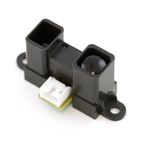
Our sensor will look like this:

The IR transmitter is located on the "depressed" side (left). The other side is our receiver. We also make another run-time measurement, so to speak. The infrared is reflected and reflected back and detected by the sensor.
Operating principle
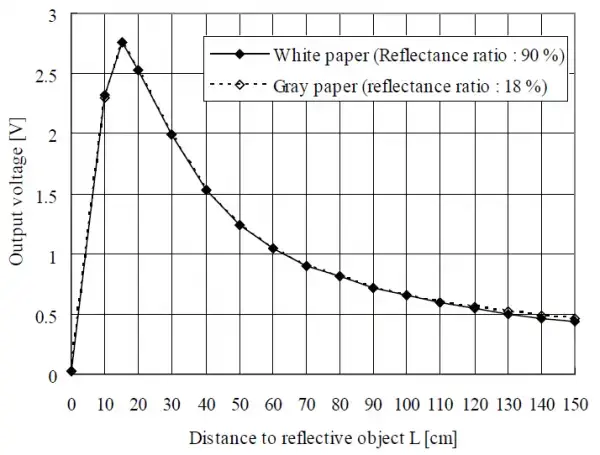
This IR sensor needs an input voltage between 4.5V and 5.5V, so it can be operated perfectly with the 5V of the Raspberry Pi. According to the datasheet there is a different voltage at the data pin, depending on how far the object measured by the sensor is. This is visible in the following graph:

Based on the voltage, the distance between approx. 15cm and 150cm can be derived relatively accurately.
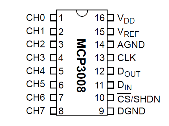
Since the outgoing voltage is analog, we first have to "translate" it with an analog-digital converter so that we can evaluate it with the Raspberry Pi. This is best done with a MCP3008 ADC.

This device is controlled via the SPI bus of the Pi and has eight channels where analog voltages can be translated. These are divided into 2^20 so 1024 ranges (0-1023). If the MCP3008 is connected to 3.3V, a signal of 1 corresponds to 0.00322V (3.22mV). Since the SPI bus of the Raspberry Pi works on 3.3V, no more voltage should be applied, otherwise the GPIOs can be damaged.
Wiring it to the Raspberry Pi
The whole circuit schematically looks like this:

The result is:
Raspberry Pi |
MCP3008 |
Pin 1 (3.3V) |
Pin 16 (VDD) |
Pin 1 (3.3V) |
Pin 15 (VREF) |
Pin 6 (GND) |
Pin 14 (AGND) |
Pin 23 (SCLK) |
Pin 13 (CLK) |
Pin 21 (MISO) |
Pin 12 (DOUT) |
Pin 19 (MOSI) |
Pin 11 (DIN) |
Pin 24 (CE0) |
Pin 10 (CS/SHDN) |
Pin 6 (GND) |
Pin 9 (DGND) |
The distance sensor has only three connections: Red (5V), Black (GND) and Yellow, which is the data pin and connects to the MCP3008 ADC. For some people this might ring alarm bells and say why a 5V module is connected directly, although the Pi's SPI bus is not allowed to get more than 3.3V input. The datasheet states that the output voltage of the sensor never goes above 3V (see graph from the datasheet). If you are still afraid that something could happen to the Pi, you can put a voltage divider with 2 resistors in front of it, but this will decrease the accuracy and also my used formula would have to be recalculated. In my tests I never got voltages above 2.7V (GP2Y0A02YK0F). With the other Sharp sensors this can deviate possibly.
Preparations on the Raspberry Pi
To be able to control the MCP3008, the SPI (Serial Peripheral Interface) bus must be activated. This is done as follows:
sudo raspi-config
"8 Advanced Options" -> "A6 SPI" -> "Yes".
After that you have to confirm the reboot.
In some cases the module (spi-bcm2708) must also be added to the /etc/modules file. To do this simply
sudo nano /etc/modules
and add the following line at the end (if it is not there):
spi-bcm2807
Now you can install the spidev library if you haven't already done so:
sudo apt-get install git python-dev git clone git://github.com/doceme/py-spidev cd py-spidev/ sudo python setup.py install
Programming the distance measurement
We now create our Python script:
import spidev

spi = spidev.SpiDev()
spi.open(0,0)
spi.max_speed_hz=1000000


def readChannel(channel):
  val = spi.xfer2([1,(8+channel)<<4,0])
  data = ((val[1]&3) << 8) + val[2]
  return data

if __name__ == "__main__":
  v=(readChannel(0)/1023.0)*3.3
  dist = 16.2537 * v**4 - 129.893 * v**3 + 382.268 * v**2 - 512.611 * v + 301.439
  print "Distanz: %.2f cm" % dist
What happens here exactly? First of all the analog value (between 0 and 1023) is read out (line 15). But since we want to know the voltage, the value is divided by 1023 and multiplied by 3.3 (volts).
Attention: In this case we know (according to the datasheet) that the output voltage never goes above about 2.8V, although we supply the sensor with 5V. Other modules (analog as well as digital) often return signals with voltages as high as the applied voltage. If you don't pay attention to this, it can cause damage to the Raspberry Pi.
In line 16 of the script I convert the voltage into centimeters. I found the formula for this here and adapted it a little. For this I tested different distances and changed the factors a bit, so that the calculated distance is as accurate as possible. As I mentioned in the beginning, this formula is only for the Sharp GP2Y0A02YK0F sensor. Since the other sensors provide analog signals in a similar range, this formula has to be adapted for the corresponding sensors.
We learned how to connect an analog sensor to a digital Raspberry Pi. For this we need an analog-digital converter. Also we have learned how to activate the SPI bus and work with it. Finally, we learned how to work with an infrared distance sensor and determine a distance to an object.
In the next chapter, we'll look at Speed measurement with IR sensor GP2Y0A02YKOF (Python).
